

01. Introduction: Noise and Distortion Are Mostly Structural Diseases
A system humming the moment it powers on, sound breaking up on big dynamics — most people suspect equipment class first. Take the faulty system apart and the truth is usually simple: one stage pushed to the edge of clipping, or another idling down in the noise zone.
Gain structure is the allocation of levels across every stage of the signal chain. It decides three things: how low the noise floor sits, how much peak headroom remains, and where distortion is born. Equipment only sets each stage's capability ceiling; structure decides how much of that capability is actually used.
This article gives a workable method: read the level window of each stage, recognize the difference between the two structures, verify stage by stage with a unified reference level, and walk the five-step process to delivery.
02. Level Windows: Every Stage Has Two Lines
Every audio stage is sandwiched between two lines: its own noise floor below and its clipping point above. The usable window between them is typically about 60 dB — work too low and the noise gets amplified downstream; work too high and the first peak clips.
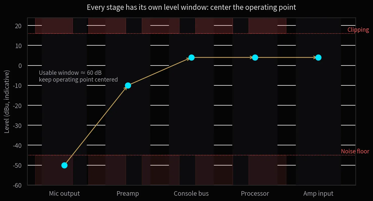
Figure 1
Level windows along the chain: microphone output starts around -50 dBu, the preamp lifts it cleanly, and the whole line then runs at the +4 dBu reference — operating point centered, margin kept at both ends.
A microphone outputs around -50 dBu (a fragile signal, most vulnerable to interference), and the preamp's job is to lift it cleanly to line level. From console buses through processors to amplifier inputs, professional gear is designed around the +4 dBu reference level — the common language of the entire chain.
The structural principle in one sentence: every stage outputs the same reference level, and neither attenuation nor extra amplification happens mid-chain. Whoever breaks that consistency invites noise or distortion in.
03. Right Versus Wrong: Two Structures, Two Sounds
The most common wrong structure: preamp gain cranked to the top, then every downstream stage attenuating to compensate. Once the preamp clips, distortion is recorded into the signal; attenuating afterwards only makes the distorted sound quieter, not cleaner. Meanwhile downstream stages work in the low-level zone where noise occupies a larger share — losing on both distortion and noise.
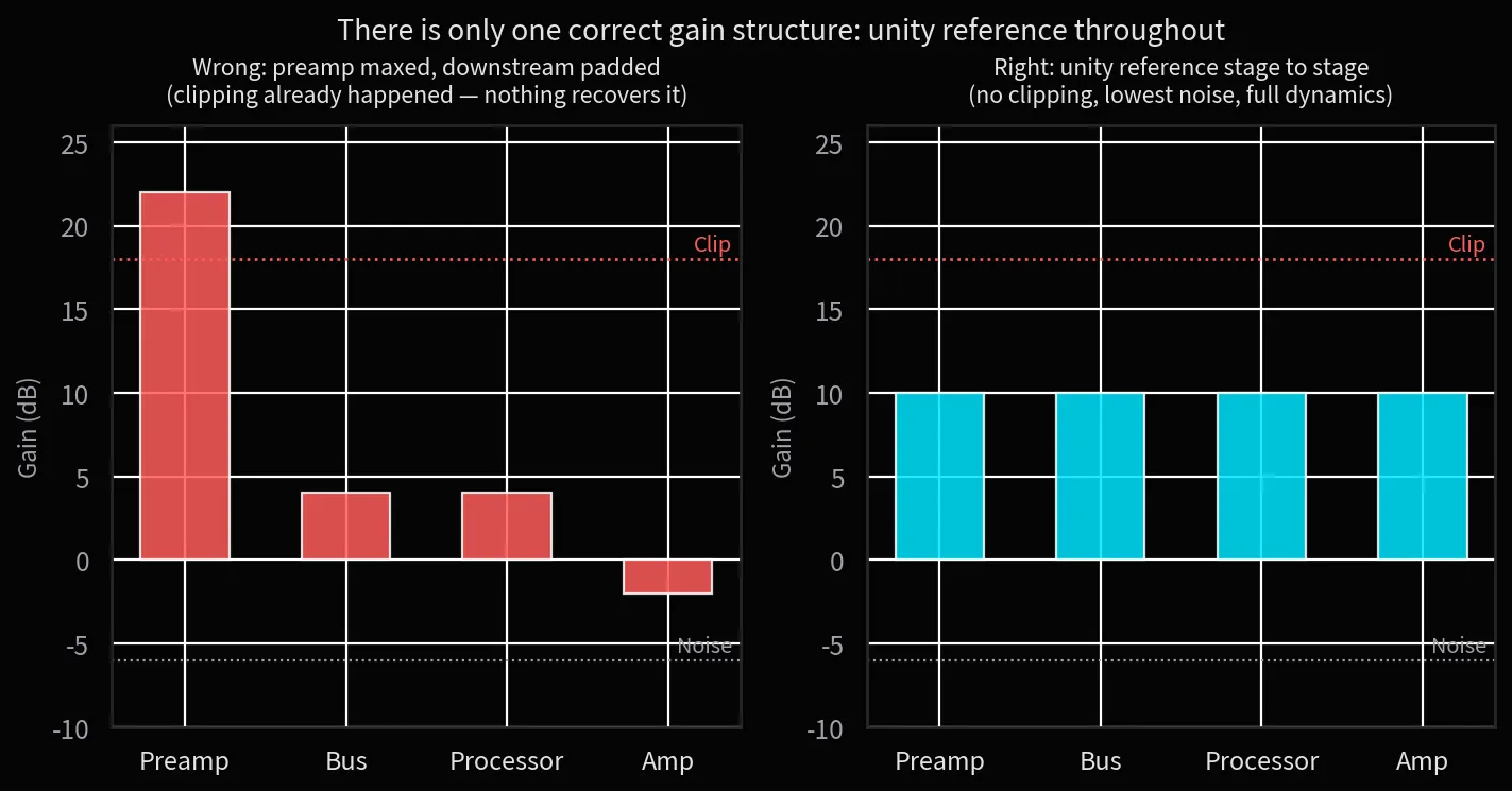
Figure 2
Right versus wrong: on the left the preamp is maxed and later stages attenuate — clipping has already happened; on the right every stage shares one reference, margin is distributed, dynamics stay intact.
The correct structure: set preamp gain from the microphone's measured maximum output with at least 12 dB peak margin, pass every subsequent stage at the same reference level, and match amplifier sensitivity to loudspeaker power back-calculated from the SPL targets of GB 50371.
The fastest health check of a system's structure: feed pink noise at reference level through the whole chain and read every meter. Whichever stage reads abnormally is where the disease lives.
04. The Unified Reference-Level Method: Stage-by-Stage Verification
The only tools needed are a signal generator (or the console's built-in oscillator/pink-noise source) and the meters on each stage. The flow: start at the source, send 0 dBu or +4 dBu pink noise, and verify input and output readings stage by stage — each stage should pass the same reading with neither loss nor overload.
Three common traps: ① confusing channel gain with faders — gain sets the preamp window, faders set mix balance, and using faders to compensate for insufficient gain is drinking poison to quench thirst; ② default processor input sensitivity — many DSPs ship at the consumer -10 dBV setting and overload instantly on a +4 dBu line, so switching the input stage is the first thing to do in any system; ③ inconsistent amplifier sensitivity — mixing 0.775 V and 1.4 V sensitivity amplifiers without re-trimming gain guarantees SPL mismatch.
Digital links (Dante/AES67) follow the same logic: the dBu window becomes a dBFS window, with +4 dBu aligned to a -18 dBFS or -20 dBFS reference — the analog-to-digital alignment point must match, or the digital domain clips just the same.
05. The Delivery Process: Five Steps Before It Counts
The complete delivery process for gain-structure verification, each step with a defined artifact:
① Chain inventory: draw the full signal-flow diagram and mark every gain point — output: chain diagram.
② Unified reference: fix the line reference (analog +4 dBu / digital -18 dBFS) — output: reference table.
③ Stage-by-stage alignment: align meter readings with pink noise — output: verification record.
④ Margin check: peak headroom ≥ 12 dB, measured noise floor in spec — output: margin test sheet.
⑤ Measured acceptance: maximum SPL and total system noise per GB/T 4959, plus listening review — output: acceptance sheet.
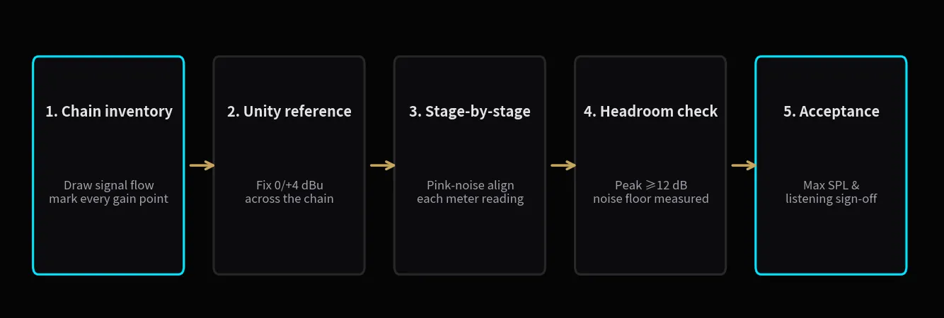
Figure 3
The five-step verification process: every step has a defined artifact, turning level management into an acceptable engineering action.
The essence of this process is turning "does it sound good" from subjective opinion into stage-by-stage readings.
Good sound is managed level by level. Draw the chain clearly, unify the reference, align every stage, keep the margin generous — with gain structure right, mid-tier equipment can deliver top-tier sound.