
01. Architectural Acoustics Before Electroacoustics
No sound system can rescue a bad room. The usual suspects in report halls are excessive reverberation time, flutter echoes between parallel walls, and high HVAC noise. With any of these present, speech stays muddy no matter how good the loudspeakers are.
The correct engineering sequence is: verify the room's reverberation time first (0.8–1.2 s mid-frequency unoccupied is a reasonable target, depending on volume), design absorption into walls and ceiling, seal sound leakage from doors, windows and equipment rooms — and only then move into electroacoustic design. Any proposal that talks loudspeaker brands before room conditions deserves scrutiny.

Figure 1
Wall-mounted acoustic elements: the first line of defense in reverberation control.
02. Fix the Metrics Before the Equipment
Under GB 50371-2006 (Code for Sound Reinforcement System Design in Halls), key acceptance metrics for report halls should be anchored at: speech transmission index STI ≥ 0.55 (≥ 0.60 for important halls), maximum sound pressure level ≥ 103 dB, and sound-field non-uniformity ≤ 8 dB.
Write the metrics into the proposal and the contract, then verify them on site per GB/T 4959-2011 (Measurement Methods for Sound Reinforcement Characteristics in Halls). This protects both the owner and the contractor.
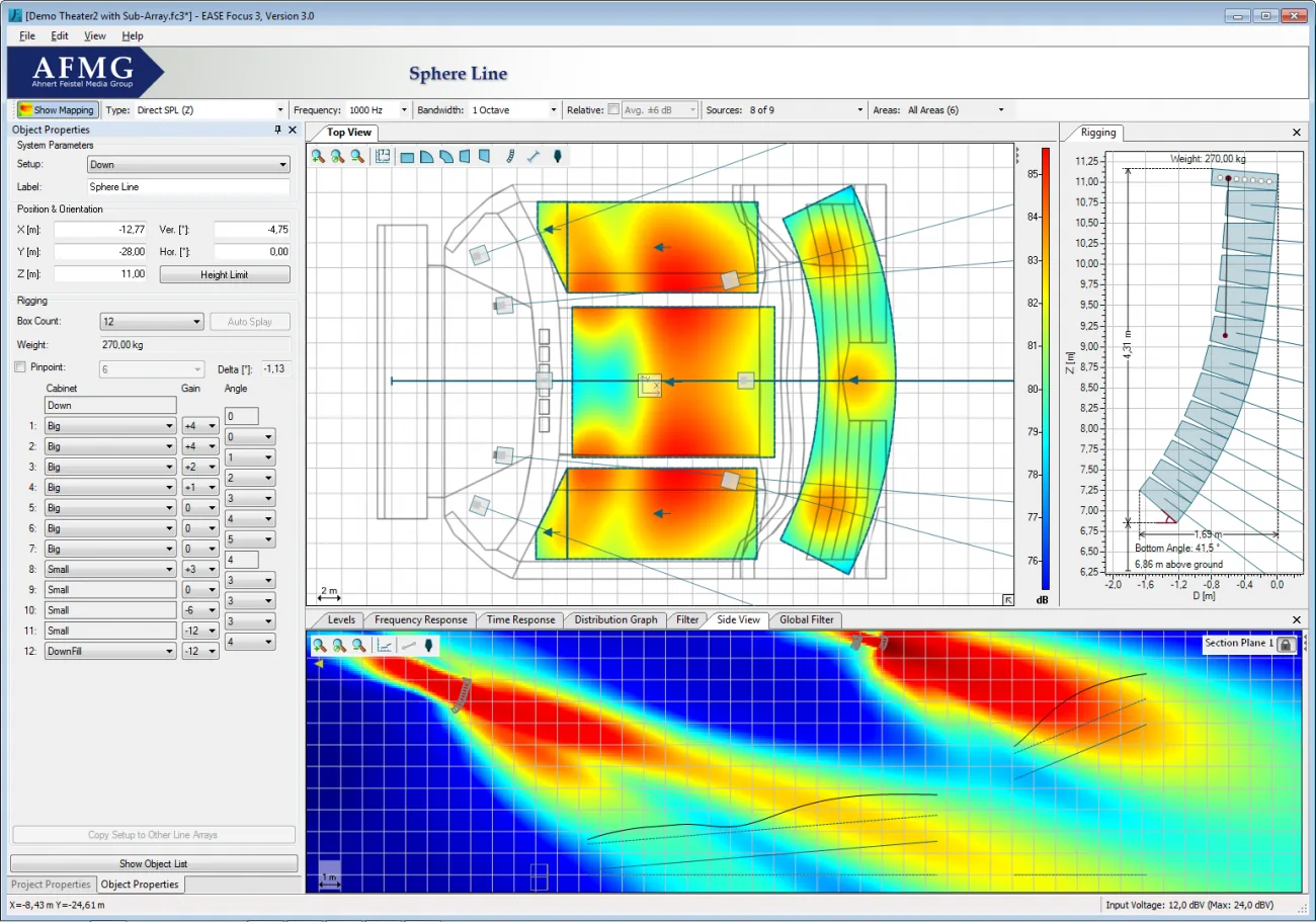
Figure 2
Acoustic simulation: coverage uniformity is visible at the drawing stage.
03. Loudspeaker Selection: No Best, Only Best-Fit
| Layout | Best For | Engineering Notes |
|---|---|---|
| Line array | Large volumes, high ceilings, deep audience areas | Rigging load calculations and coverage-angle modeling come first |
| Distributed point source | Small/medium halls, low ceilings | Lip and rear fills remove shadow zones; delays aligned to mains |
| Column speaker | Meeting rooms, houses of worship, live rooms | Narrow vertical dispersion keeps energy off reflective surfaces |
Subwoofers belong only where they are justified: a speech-dominant report hall does not need deep low-frequency extension; a multi-purpose hall hosting performances does, at the dual-18-inch class.
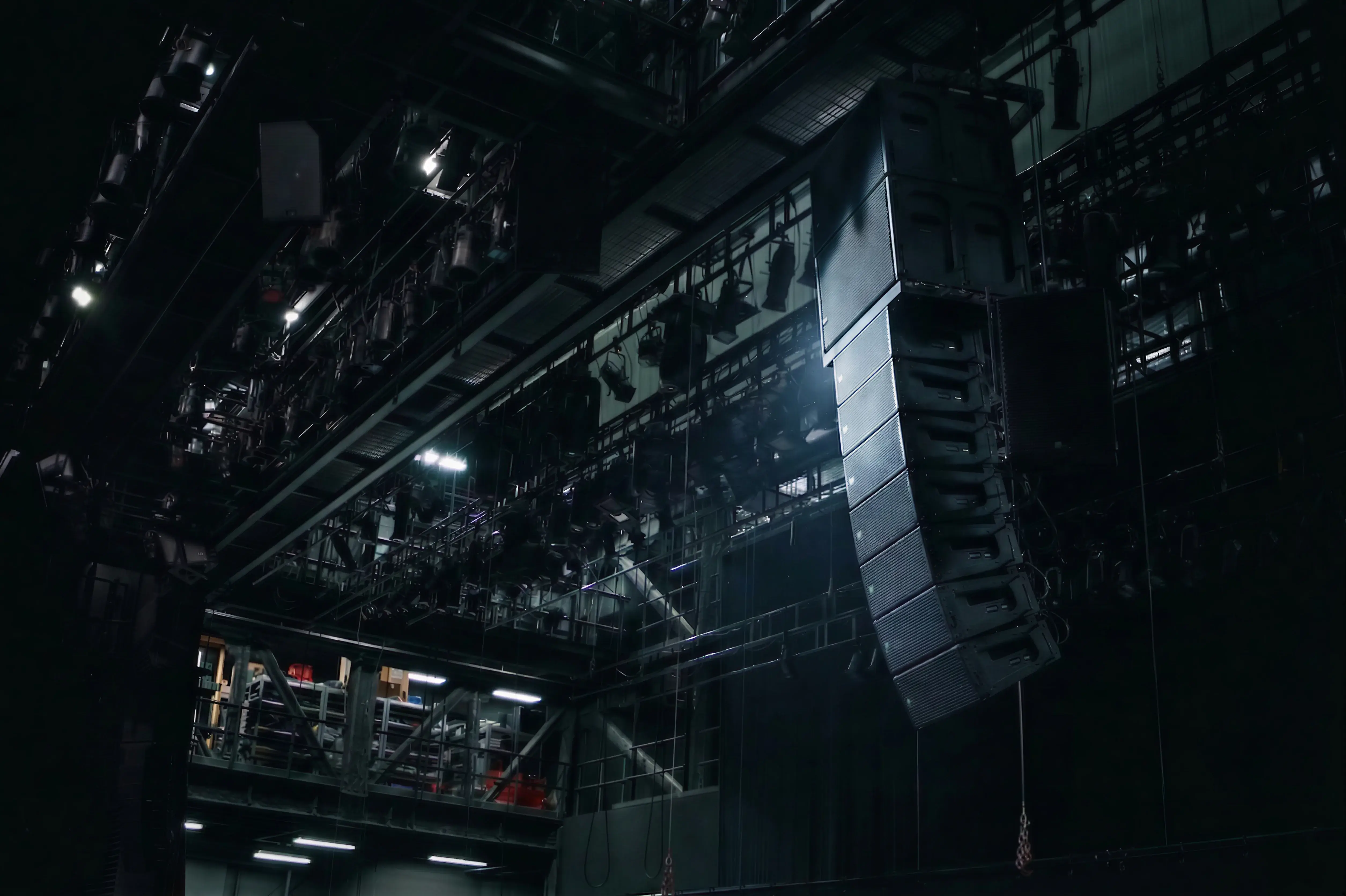
Figure 3
Line-array rigging: coverage angles and load verification come first.
04. Power Matching: Arithmetic People Keep Getting Wrong
Engineering convention: usable amplifier power ≥ total rated loudspeaker power × 1.2 (with the amplifier side rated at 8 Ω and derated a further 20% for headroom).
Example: 8 mains × 600 W, 6 fills × 300 W, 2 subs × 1,200 W — roughly 9,600 W rated, calling for at least 11,500 W of usable amplifier power. The arithmetic is simple, yet a large share of bid proposals fall below this line; clipping and burned HF drivers during commissioning usually trace back to exactly this.
The surrounding chain needs verification too: does the DSP have enough input/output channels for every loudspeaker zone, and have the wireless microphone frequencies been scanned on site?

Figure 4
The power and processing core in the rack: headroom is the premise of reliability.
05. Acceptance and Operation: Delivery Is Not the Finish Line
Commissioning records (EQ, delays, limiter thresholds) should be handed over as-built documentation. Inspect rigging and connectors quarterly, re-measure acoustic metrics annually, and write operator training into the contract — otherwise you get a great system that nobody can run.
A report hall that sounds right is the product of disciplined sequence: room first, metrics second, selection third, power fourth, acceptance last. Follow the sequence and the equipment list almost writes itself.